Thoughts on hardware debugging
Posted on Sun 11 September 2022 in MUPS16
- The control lines are designed with a couple of common features:
- they all have a safe or no-op state when the lines are high. For simple lines, this means that they are active-low. For encoded lines, this means that all ones is a no-op command
- they all have pullup resistors on them, so that if nothing is driving them they revert to their safe state.
The idea is that we should be able to put the CPU into a state where nothing is driving any of the control lines, and they we can have external circuitry (e.g. an Arduino, or a dedicated piece of hardware) that can drive the control lines as necessary to read or write register contents, read memory, etc. To make this work, we need some way to force the control unit to put all lines into a high-Z state.
The simplest option to implement would be to have an external debug line that the debug hardware can pull low whenever it wants to drive the control lines, and all control lines are fed through driver chips that have 3-state outputs, controlled by this debug line. This has a couple of obvious problems though: first, we need a lot of driver chips, and they take up a lot of room. More importantly, how do we syncronise the debug line with the CPU operation so that it doesn't happen part-way through a cycle, when it might put the CPU into a bad state?
Another option, which is what I'm implementing, is to take advantage of the fact that there's a natural period at the start of every cycle in which we don't really want to be driving the control lines anyway. Since most (all?) lines are controlled, either directly or indirectly, by the contents of the microcode RAM chips, and since all RAM chips have a small period after their address lines change in which the outputs are undefined, it is dangerous to drive the control lines immediately after the clock goes high, as the output of the RAM chips will be unstable. For example, between cycle 3 and 4 of a WB instruction, we have something like:
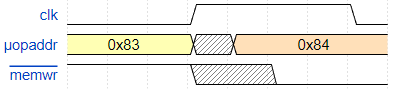
During the shaded period the value of memwr is undefined, and could change potentially change multiple times. One way to both avoid this, and to give us a period in which a debugger can drive the control lines, is to have the control lines released (in a high-Z state) whenever the clock is high:
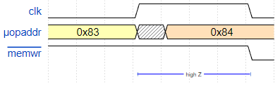
The downside is that the control line will not change until halfway through the cycle, meaning we'd have to extend the clock period accordingly to allow the rest of the system to complete its operations in the second half of the cycle.
This, too, can be fixed by looking at the relative timing requirements of the control unit, and the rest of the system. Since we're using 10ns SRAM for the microcode, and allowing for the maximum propagation delay of any gates that post-process, demux etc. those RAM outputs to produce the final control signals, we still only need about 50ns to produce a stable control signal. Since the maximum clock we're aiming for here is 4 MHz, which is a 250ns period, we can afford to have a very asymmetric clock, in which we have a short high pulse and a long low one:
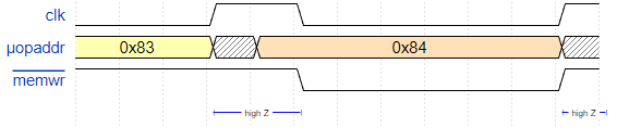
With this setup, we can just use the clock as the debug signal. When it's high, all control units must leave their output lines undriven. I think this will almost be enough for a useful debugger. The main issue I'm not certain about is whether all the control signals I need are exposed on the backplane. For example, I don't think there's currently any way to set the pc register via the tester card, since it doesn't function exactly like a normal register: you cannot set it by setting regrdidx to 14 and regrd low. Instead, it's controlled by a 3-bit pcop signal, which has 5 separate values that set pc, from the immediate unit, or from the data bus, with various conditions. This was simple to implement, but it might make it impossible to control pc from the debugger, which is a shame. This will need some thought.