Debugging decrement bugs (round 2)
Posted on Mon 12 May 2025 in MUPS16
A few months ago I was trying to track down a bug that mainly seemed to affect decrementing r1 from 255 to 0, where the register value would occasionally jump to a more-or-less random value part-way through the decrement sequence. I never did get to the bottom of it, and the bug went away of its own accord shortly after. I was pretty convinced that it was a bad solder joint on the register, since it only affected that one, and it also seemed to show up much more frequently when it was cold.
Well, that was all completely wrong. While I was trying to debug my LCD display the bug came back, and this time I'd refactored my code slightly so the first big decrement loop used r4, and lo and behold, the bug showed up there. The room was also about 27°C. Probably not a bad solder joint, then. Since the bug was very reproducible this time I decided to grab the chance to debug it properly.
For reference, this is the problematic code that was running whenever this bug hit (it's initialising a range of entries in the page table for the main kernel process, with the counter in r4):
.ptset:
    ptse r1, r3
    addi r1, r1, 1
    addi r3, r3, 1
    addi r4, r4, -1
    bnz  r4, .ptset
Using the same tools as last time, I hooked up my logic analyser to a few interesting lines on the register card, then ran a script on my debug board that stepped the clock, reading the state of the a, b and data buses in the middle of each step. When the bug happens, it gives a trace like this
0x0066 04 9f  addi  r4, r4, -1
  Step 0  data: 0x0000 bus_a: 0x0066 bus_b: 0x0000
  Step 1  data: 0x049f bus_a: 0x0000 bus_b: 0x0000
  Step 2  data: 0x0007 bus_a: 0x0008 bus_b: 0xffff      ; bus_a=r4, bus_b=-1, data=r4-1
0x0068 bc fb  bnz   r4, -10
  Step 0  data: 0x0000 bus_a: 0x0068 bus_b: 0x0000
  Step 1  data: 0xbcfb bus_a: 0x0000 bus_b: 0x0000
  Step 2  data: 0x0000 bus_a: 0x0007 bus_b: 0x0000      ; bus_a=r4
  Step 3  data: 0x0060 bus_a: 0x006a bus_b: 0xfff6
0x0060 f9 61  ptse  r1, r3
  Step 0  data: 0x0000 bus_a: 0x0060 bus_b: 0x0000
  Step 1  data: 0xf961 bus_a: 0x0000 bus_b: 0x0000
  Step 2  data: 0x0000 bus_a: 0xe003 bus_b: 0x0001
0x0062 01 21  addi  r1, r1, 1
  Step 0  data: 0x0000 bus_a: 0x0062 bus_b: 0x0000
  Step 1  data: 0x0121 bus_a: 0x0000 bus_b: 0x0000
  Step 2  data: 0xe004 bus_a: 0xe003 bus_b: 0x0001
0x0064 03 61  addi  r3, r3, 1
  Step 0  data: 0x0000 bus_a: 0x0064 bus_b: 0x0000
  Step 1  data: 0x0361 bus_a: 0x0000 bus_b: 0x0000
  Step 2  data: 0x0002 bus_a: 0x0001 bus_b: 0x0001
0x0066 04 9f  addi  r4, r4, -1
  Step 0  data: 0x0000 bus_a: 0x0066 bus_b: 0x0000
  Step 1  data: 0x049f bus_a: 0x0000 bus_b: 0x0000
  Step 2  data: 0xfffe bus_a: 0xffff bus_b: 0xffff      ; bus_a=r4, bus_b=-1, data=r4-1
Here we can see that initially, r4 has the value 0x8. We output it to the a bus (blue), decrement it, and save it back (purple). On the next instruction, we again output r4 to check if it's zero, and it still has the correct value (0x7, in blue). The next time we see r4, though, a few instructions later, the value is suddenly 0xffff, even though we haven't touched it in between.
This pattern had been confusing me for a long time, until I finally managed to get my logic analyser hooked up to the correct set of pins at the right time, and caught this trace:
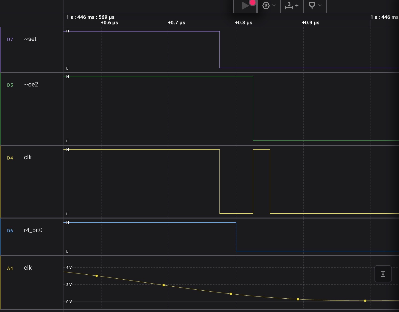
This shows the clock line spiking high again approximately 50ns after it dropped low (it's hard to be precise, since this is starting to rub up against the limits of resolution on my logic analyser). This is Not Good News. It explains why we see the weird behaviour in the trace above: shortly after the clock goes low, the control unit starts driving lines, and set line goes low. Shortly after that, and long before the end of the cycle (and before the data lines have had a chance to settle), the clock blips high for an instant, so the active register snaps whatever transient values are on data.
This also explains why I only see this problem when decrementing a register: if I was storing the result into a register that wasn't also one of the inputs then it wouldn't matter if it latched the wrong value part-way through the cycle, since it would correct itself at the end. In this case, though, the value of the destination register is also one of the sources, so that incorrectly-snapped value now gets fed into the ALU and corrupts the computation.
I'm not really sure what could be causing this. I will have to do some debugging of the clock signals, but at least it's progress of a sort.