Debugging noisy clock signal, part 2
Posted on Thu 29 May 2025 in MUPS16
A couple of days ago I managed to get the clock looking much better with some capacitors and a small smoothing resistor. So, armed with my new oscilloscope, it was time to hook it back up to the rest of the system and see how things worked.
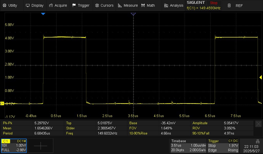
Short answer: they didn't. The decrement bug was still there. So, time for more debugging. As a reminder, this is what the clock looked like before I hooked it up to everything else:
After connecting it to (almost) the full computer, the signal degraded significantly:
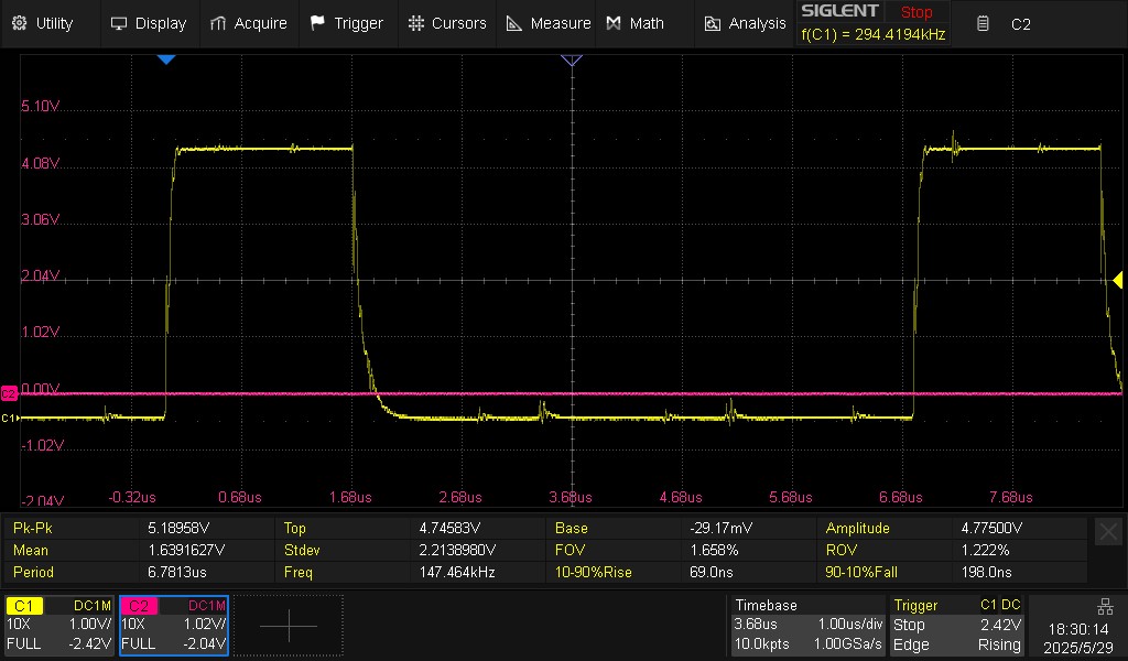
and in detail, showing the bounce on the rising and falling edges:
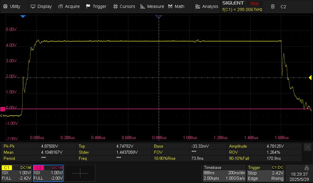
Note that this is with the register unit removed, since I had taken it out for some earlier debugging shortly before capturing these traces (it had no effect).
My suspicion was that it was the ALU. That board has two potential issues:
- a lot of the decoupling caps are missing from this board, as I had to remove them one-by-one to find a short-circuit earlier (a solder bridge under the capacitor - not fun to find);
- the control signals are pulled high by a 10KΩ resistor when they are not driven (while the clock is high), which might be too high to pull them up in time. Could this mean that components are fluctuating as the signal sits in the dead zone between 0.6V and 2V, and causing excessive power draw?
Sure enough, the next trace shows a very slow rise in the control signal (in purple - I picked one of the four ALU control lines at random to sample). This would need fixing regardless of whether it's causing issues, as it barely has time to make it to 5v with the clock running at only 150KHz. As an aside, I might need to rethink having the control line undriven when the clock is high, which was only ever a debugging aid.
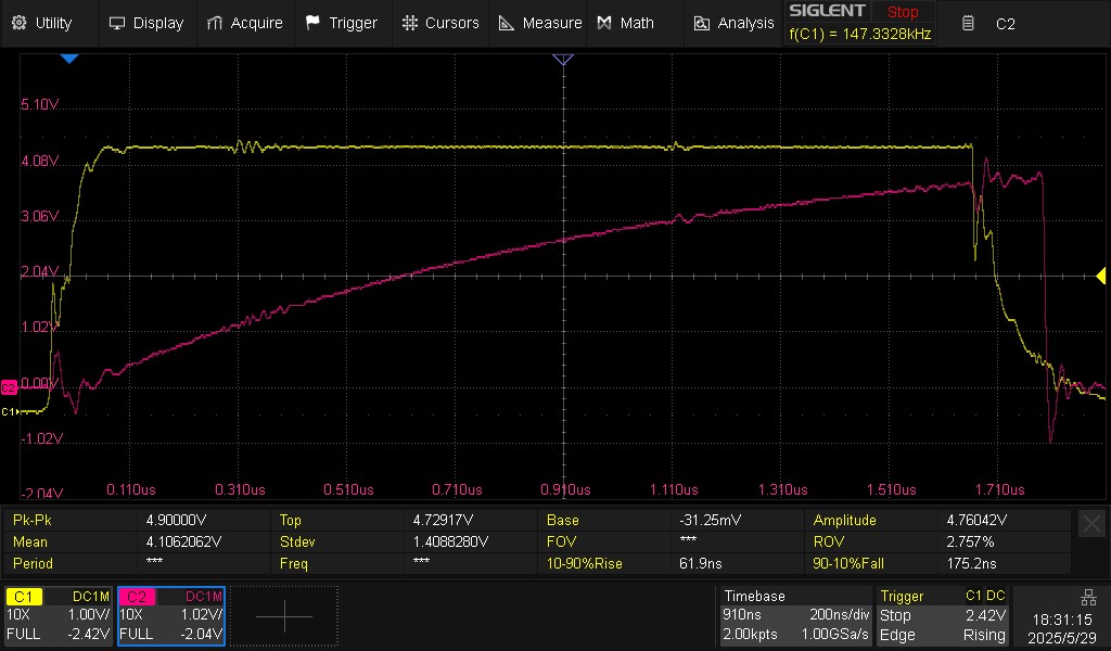
Out of interest I also sampled one of the ALU outputs to the data bus, to see when it changed, and if it fluctuated:
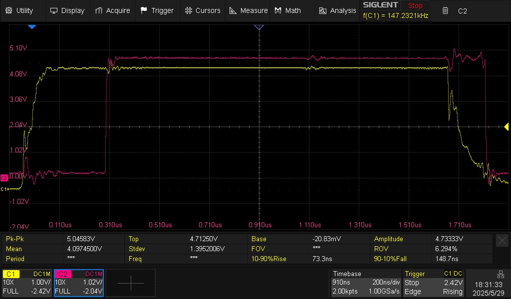
No obvious fluctuations, but it didn't go high again after the start of the cycle for about 290ns after the clock started rising, which is much longer than I expected.
One final attempt at debugging the ALU was to see if changing the default for the ALU control signals from 0000 to 1111 made any difference. Having the default be low means that if the ALU is not used in a given cycle the control unit drives it low when the clock is low, and then releases it for the pullups to pull it high when the clock goes high. Changing it so the default is 1111 means that on most cycles the ALU control signals won't actually change. It would be interesting to see if this made any difference. The answer was no:
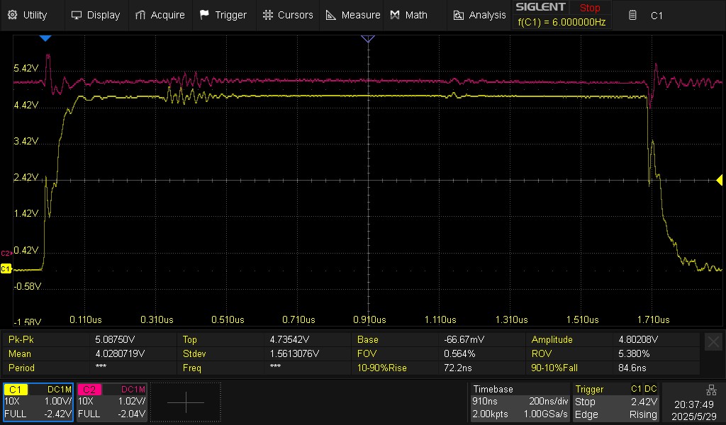
and more zoomed out:
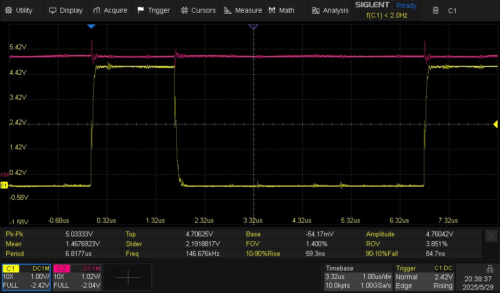
The clock bounce is still there, even when the ALU is doing nothing. As a final desperate test, I removed the ALU altogether to see if the clock improved:
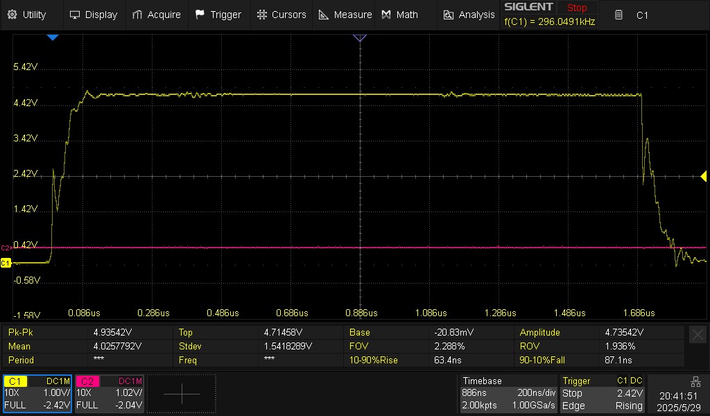
No improvement. So, all that debugging was for nothing. Given that, I tried removing basically the entire CPU (all the control units, the whole memory backplane, registers, ALU and MMU), and got more or less the same result. That strongly suggests that there's just something degenerate in the way I've designed the backplane. More debugging required. Sigh.