Memory board rev 1.1
Posted on Mon 05 July 2021 in MUPS16
I finally got a bit of time to fix the bugs in the memory and MMU boards, and to solder up the memory board (waiting for some chips for the MMU still).
- The rev 1.1 design of the memory board is alomst the same as the 1.0, except that I
- tightened up the RAM memory decoding so that it didn't respond to writes to the high memory-mapped space;
- replaced the IS61C5128AS-10TLI chips with the slightly slower IS61C5128AS-25TLI ones;
- added a set of pin headers on the left of the board that expose the MISO lines from the SPI ROM chips
The first of these was just a bug (RAM decoding was responding to _any_ write outside the ROM address space, so a write to something like the LCD mapped at 0x900000 would have written to 0x100000 as well.
The main reason for replacing the RAM chips was that I had six sitting in a box, so I didn't need to order any more. In addition, the slower chips come in a TSOP-32 package that's much more friendly for debugging (you can actually get a probe onto each leg, since they're standard 1.27mm pitch). The access time is still ridiculously over-specced for this system anyway, at 25ns.
The final change to add the pin headers was to make programming the ROM chips easier. I can now plug in a cable to program the chips, and read them back. Previously I could program them OK, but reading the contents for verification meant clipping wires directly to the MISO legs of the ROM chips, since I forgot to bring them to the board edge anywhere.
Renderings and photos
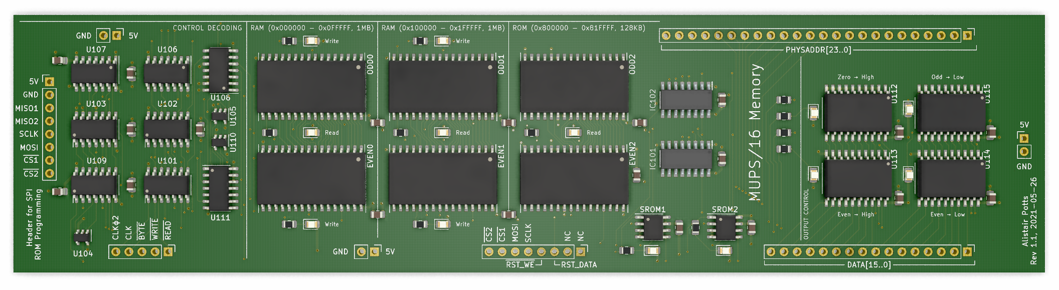
Rendering, in glorious green solder mask:
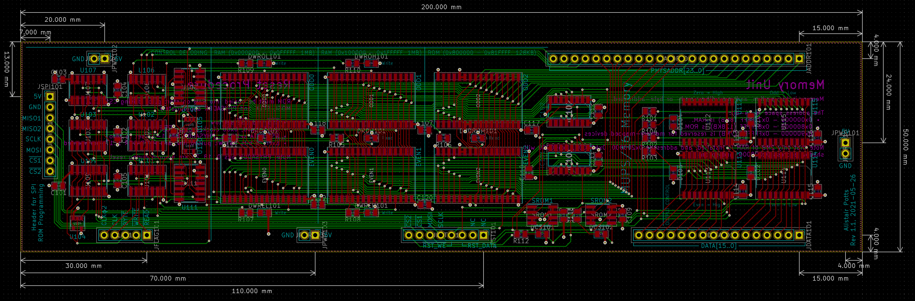
Getting a little tight on the routing here. Not quite as bad as the MMU, but close:
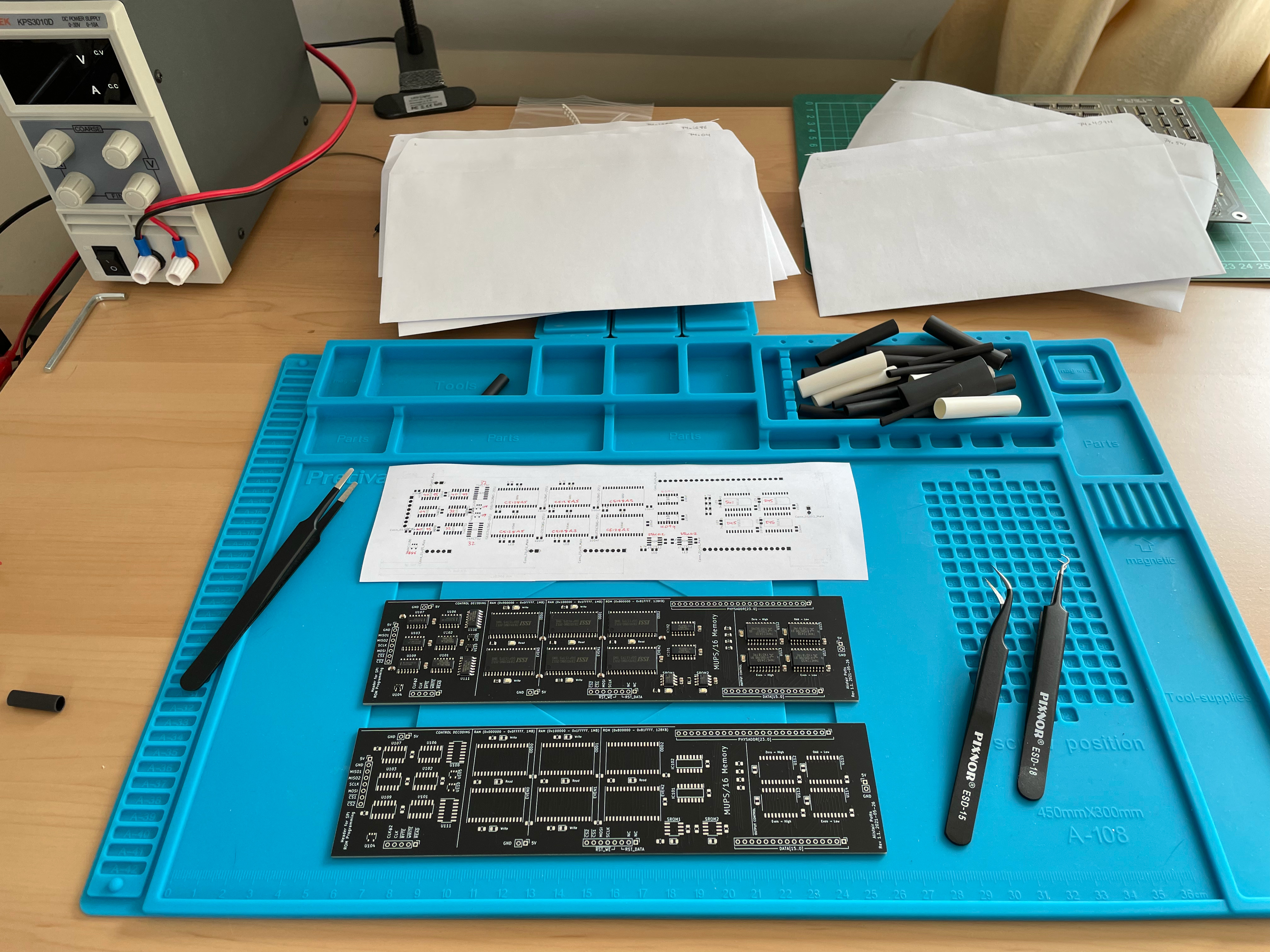
Getting ready to solder everything, with the chips laid out one one pcb before being transferred to the lower one after it's had solder paste applied:
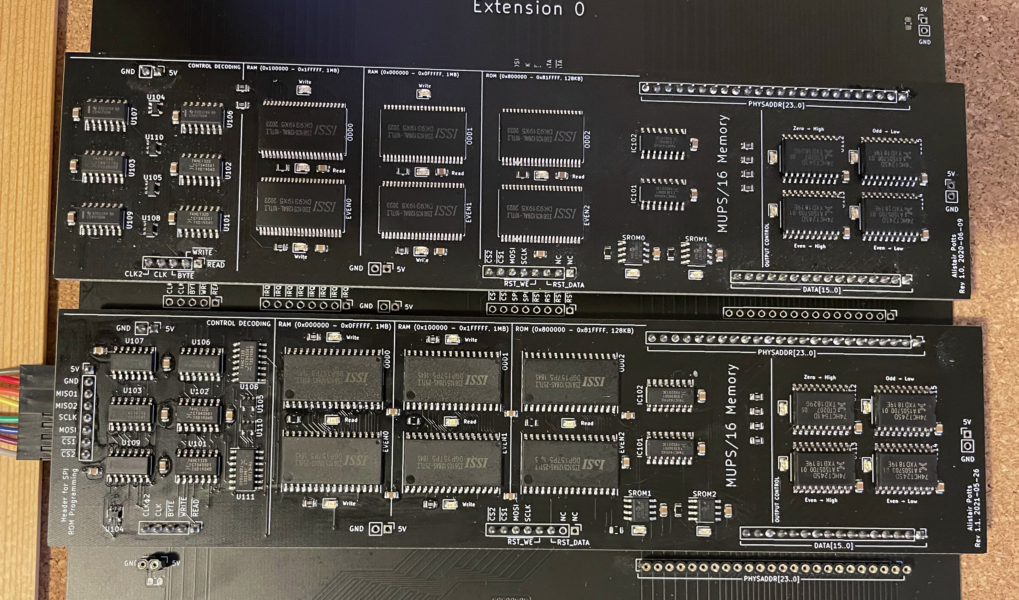
The new and old boards, side by side. I still prefer the look of the RAM chips on the old board, but the new ones are much easier to work with:
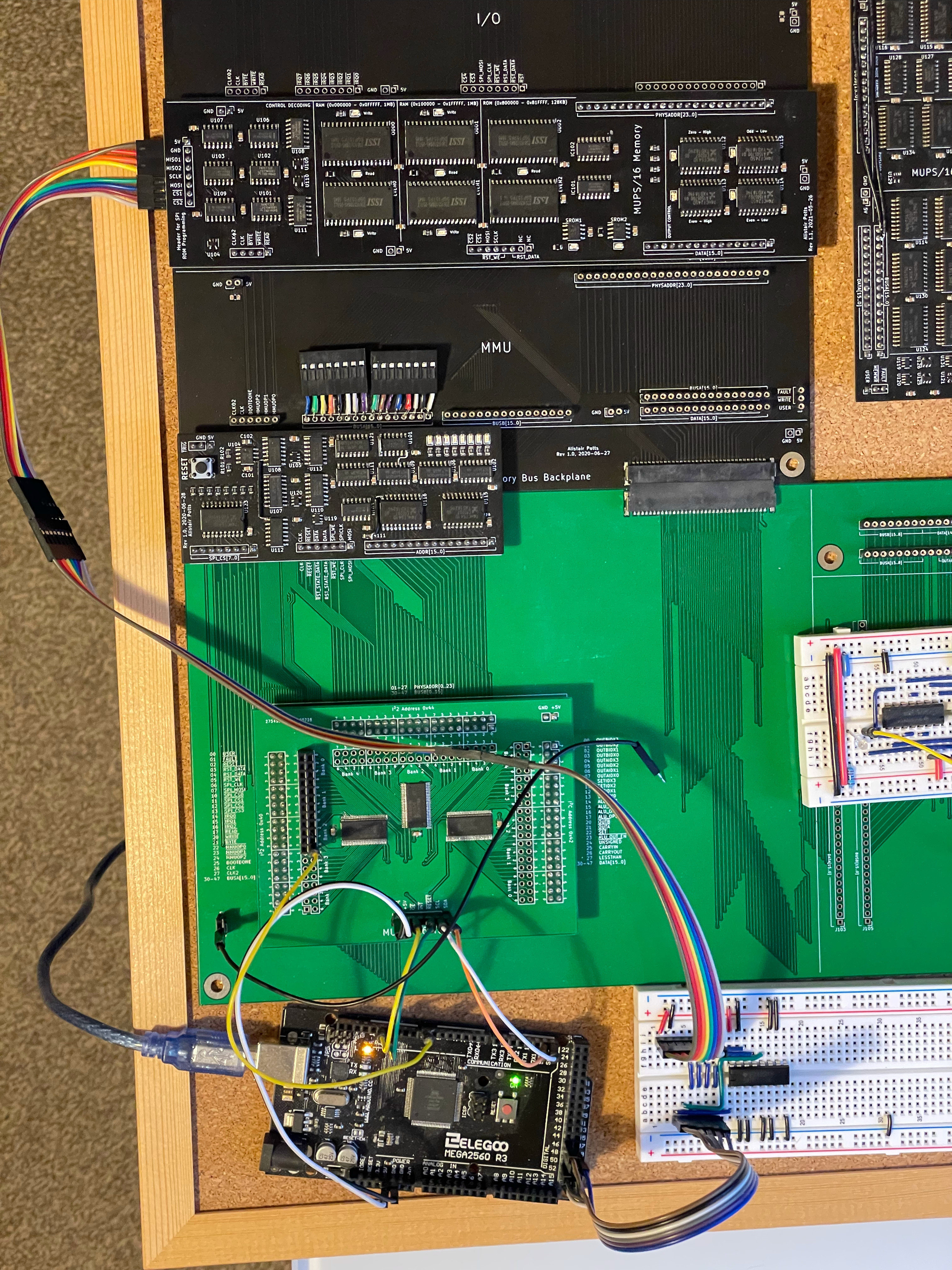
The setup for reading and writing the serial ROM chips. The extra breadboard is needed because the Arduino uses a fixed pin for the MISO line, so I needed a 2-1 mux to pick which ROM output was routed to that pin:
Testing
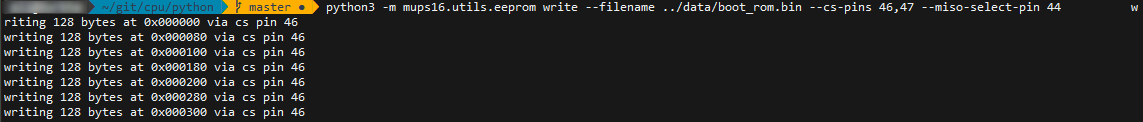
First, I tested the new setup for reading and writing the ROM chips in-place, and, somewhat to my amazement, both the hardware and software worked first time:
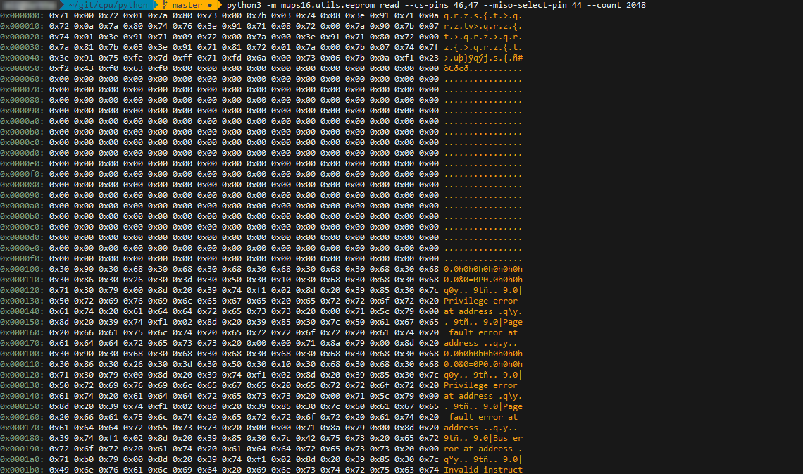
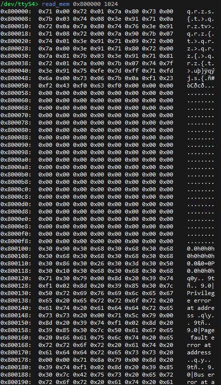
(this was writing an image containing some basic test code for the system; you can see some error messages starting at address 0x100). Since the ROM contents all looked correct, I put the reset board back in, and after a couple of seconds of the power-on-reset sequence, checked that the ROM contents had been correctly copied to RAM at address 0x800000, and hey presto:
Finally, the all-important unit testing to make sure the RAM worked, and this time everything worked perfectly!
$ python3 -m pytest mups16/test_board/mem_test.py -v -s
===========================================================================================================================
test session starts
===========================================================================================================================
platform linux -- Python 3.6.9, pytest-5.3.1, py-1.8.0, pluggy-0.13.1 -- /usr/bin/python3
cachedir: .pytest_cache
rootdir: /home/ali/git/cpu/python
collected 6 items

mups16/test_board/mem_test.py::test_ram_bytes_low_odd PASSED
mups16/test_board/mem_test.py::test_ram_bytes_low_even PASSED
mups16/test_board/mem_test.py::test_ram_bytes_high_odd PASSED
mups16/test_board/mem_test.py::test_ram_bytes_high_even PASSED
mups16/test_board/mem_test.py::test_ram_words_low PASSED
mups16/test_board/mem_test.py::test_ram_words_high PASSED
Very happy with how that all turned out. Fingers crossed the 1.1 revision of the MMU is as successful.