New breadboard clock
Posted on Fri 25 October 2024 in MUPS16
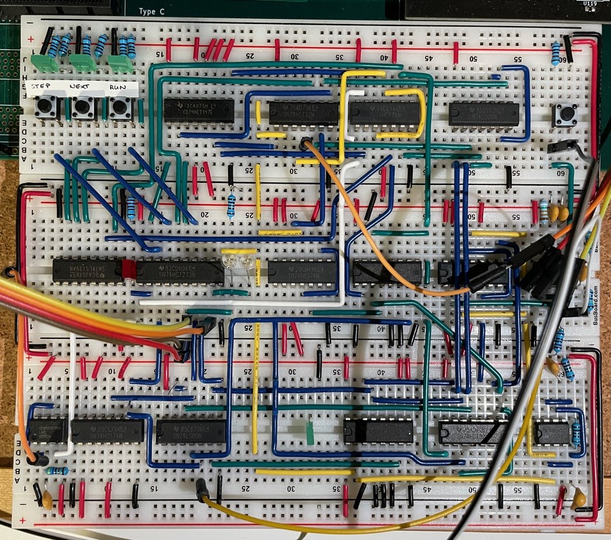
I've just finished putting together a new clock to replace the original one (which was almost a direct copy of Ben Eater's). The new one has a few nice features:
- it can generate three clock signals: the ¼-duty-cycle clock (clkq) used by the control unit, the standard ½-duty-cycle (clkh) used everywhere else, and a fast clock (clkf) that runs at four times the speed of the first two (used internally in the clock, and also intended for future use in a fast sequential multiplier in the ALU);
- it supports normal running, single-stepping through the four phases of a clock cycle (step mode), and a mode that runs at full speed until the end of the current instruction, when done is low on the rising edge of the clock (nexti mode);
- it ensures that whenever you switch from full-speed running to either the step or nexti mode the clock is stopped at the start of the first phase, with both clock signals high. This predictability is really nice for automating debugging, since it ensures that the CPU is always in a safe state with none of the control lines driven when it stops;
- all clock signals are buffered together in the same latch, to ensure that they change simultaneously, despite the clkq one having two extra gate delays;
- the reset signal is now buffered alongside the clocks, so that it too changes exactly in line with the clock, albeit one cycle later than it did before. Previously it would change approx 90µs (TODO: check?) after the clock, which added an unnecessary 90µs to the first cycle (and hence all cycles, since we can't distinguish between the first and subsequent ones).
The core of the clock is a 555 timer generating an approx 550KHz signal, which is then fed into a 4-bit 74HCT161 counter. The clkh signal is just the second bit of the counter, and the bottom two bits of the counter are used to generate the clkq signal via a not/and pair:
The counter has an enable line that we can use to control whether the clock is running. The basic logic is:
- in normal mode the enable line is low and the clock runs continuously
- in step mode the enable line goes low when the advance button is pressed, and stays low for exactly one fast clock cycle, so that the counter increments by one (moving the system clocks forward one quarter of a cycle)
- in nexti mode the enable line goes low when the advance button is pressed, and stays low until a rising edge is detected on the done line, indicating that the previous instruction has just finished
- as a final wrinkle, if reset is low then we force the enable line low, to run the clock at full speed (see 'reset' below)
This control of the enable line is implemented with a simple 4-1 multiplexer and an AND gate that forces the enable line low when the reset line is low, regardless of the multiplexer value. The multiplexer switches between one of four inputs depending on the value of its mode input. The four possibles mode values are:
- 0 - default value on power-on
- 1 - run
- 2 - step
- 3 - nexti
In modes 0 and 1 we want the enable line low, so we can just tie those inputs to ground. In mode 2, we want the input to be low for one cycle of the fast clock. We can do this with a chained pair of latches and an OR gate:
Most of the complexity in the clock comes from the mode selection, and the logic to ensure that changing the mode happens only at the start of the system clock. The actual clock generation only takes up about one breadboard; the other two are full of SR-latches and multiplexers.
I'm not planning on putting this onto a dedicated PCB yet, since I think I'll probably merge it with a respin of the reset board (which has accumulated a lot of bodges).