Reset board PCBs arrived!
Posted on Tue 18 August 2020 in MUPS16
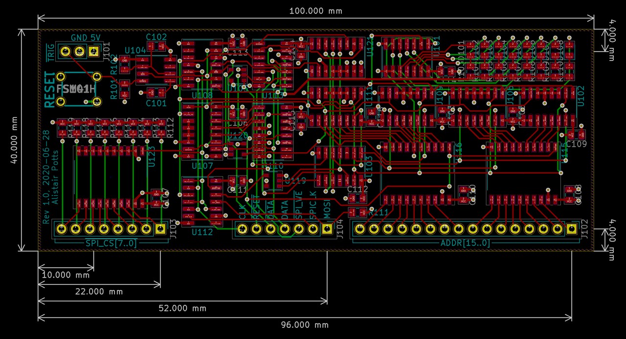
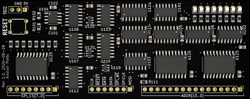
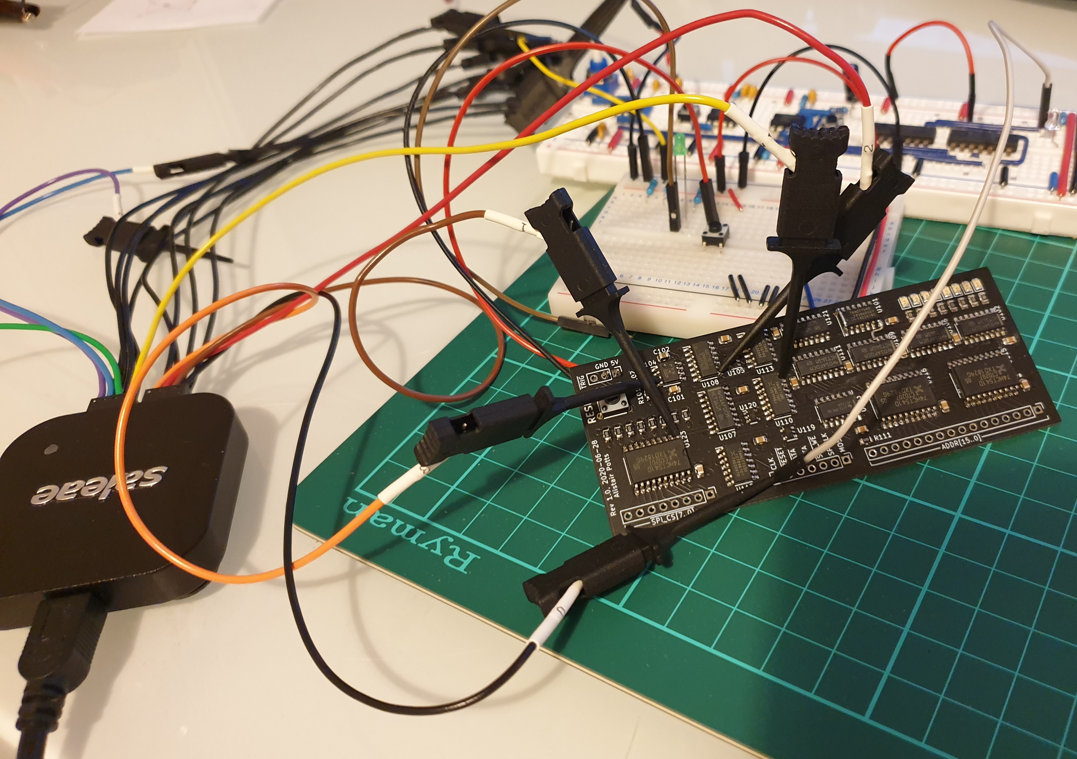
A big batch of PCBs arrived last week from China (7 different boards!), and I decided to have a go at the reset board first. This is a straightforward conversion of my breadboard prototype, so I thought it would be quick and easy to assemble and test, and I could move onto the more interesting memory boards. Well, it didn't quite work out like that. I think this board has the highest concentration of dumb mistakes per square inch so far.
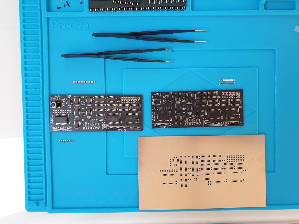
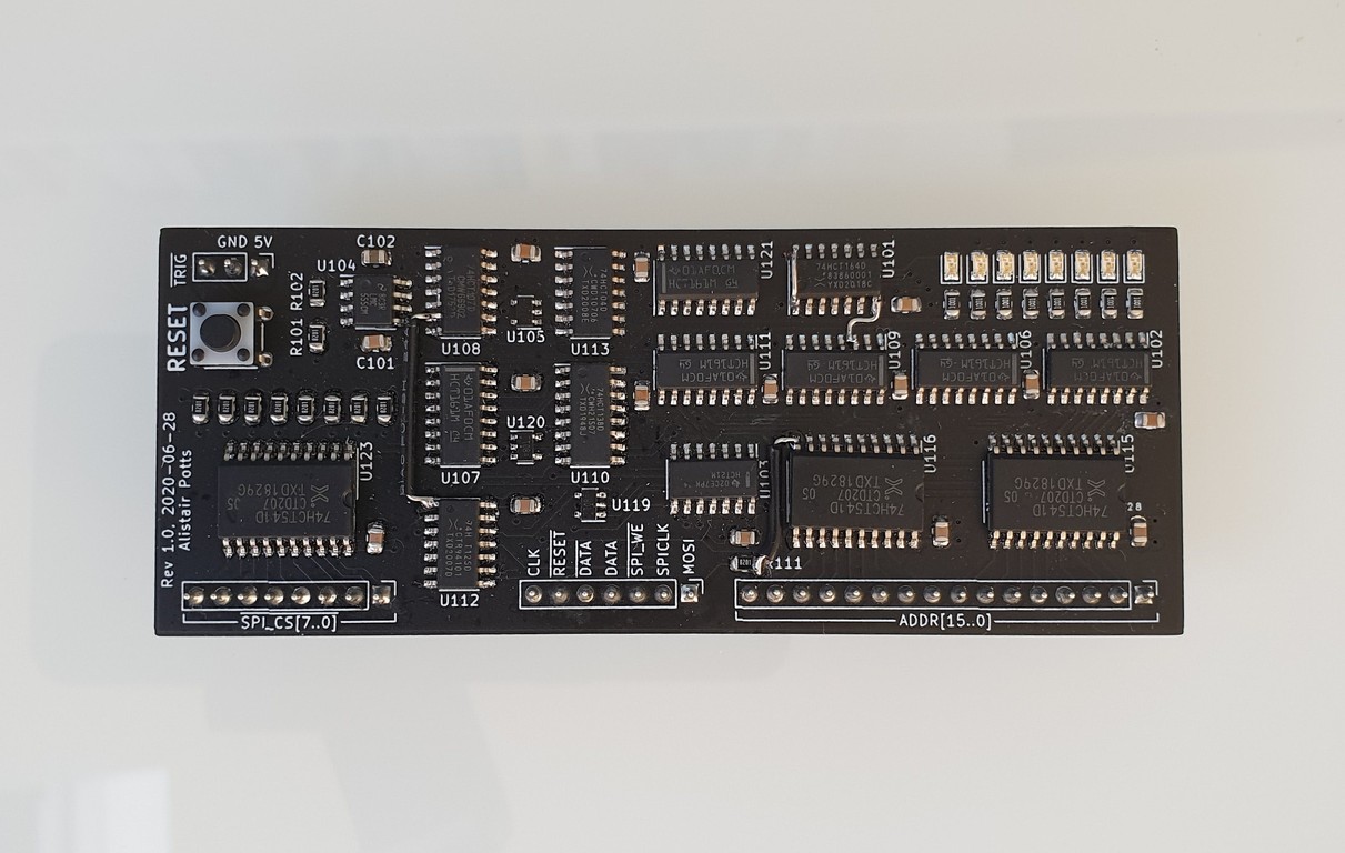
Initial assembly went quickly, and after cleaning the completed board, I hooked the breadboard clock up (I haven't converted that to a PCB yet), connected power and...nothing. Well, worse than nothing: the clock stopped ticking as soon as I connected power. Disconnect power, squint carefully at each solder joint looking for shorts, clean up a couple the might just possibly have been problems, connect again...nothing. This time, however, I noticed that the current draw on the power supply was nearly 2A, which is a crazy amount for this board.
So, there was obviously a short. Well, shorts make chips hot, right? So I should be able to tell which chip was the problem by touching them. Turned out that shorts do indeed make chips hot, and as half a fingertip fused itself indelibly to the shift register at the top of the board, I'd found my short. Looking at the schematic everything looked OK. All the inputs seemed to be connected correctly. Except (and this was my first mistake), I had used an IEEE symbol for this 74HCT164 chip because for some reason I hadn't been able to find 'normal' symbols in the Kicad symbol library:
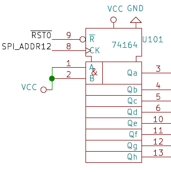
The obvious potential problem here is in the two unlabeled connectors at the top, where VCC and
GND are connected. Sure enough, looking at the symbol editor in Kicad confirmed I'd swapped the
two around:
Why the model doesn't label them in schematic view I don't know. Anyway, I put in a bodged fix for that on the board by cutting the traces from pins 7 and 14 with a sharp knife, and soldering in wires connecting them to the correct nets on nearby chips.
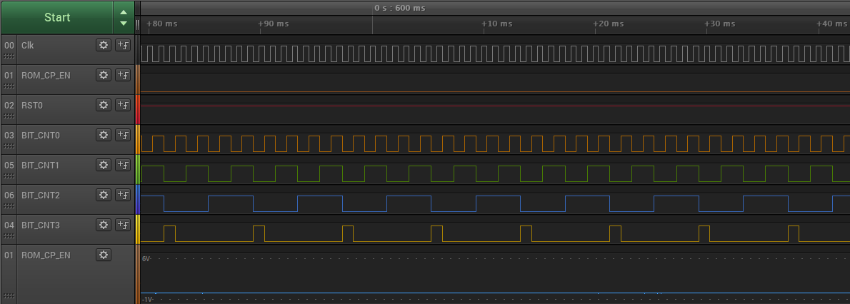
With that fixed, at least I didn't get a short-circuit any more, but I still wasn't seeing blinkenlights. Time to crack out the logic probe:
and the result:
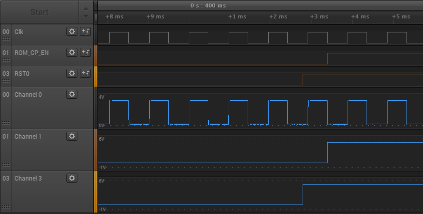
RST0 here is the signal from the 555 timer, which is low for ~150ms after power-on. The
signal labelled ROM_CP_EN here is an active-low signal that's supposed to go low at the trailing
edge of the first clock after the RST0 line returns high. Instead, it seems to be inverted:
it's initially low, and goes high on the first clock after RST0 goes high.
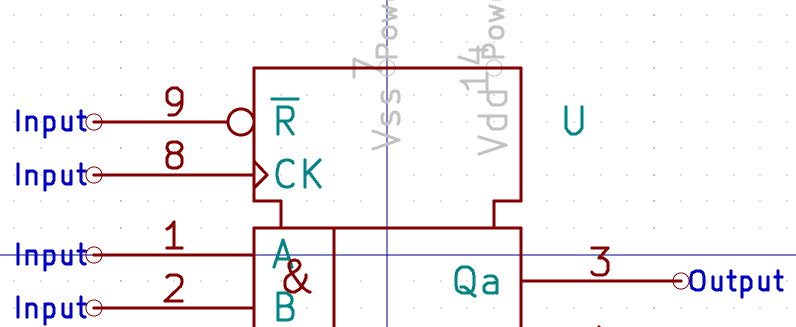
Well, this was just an easy problem to diagnose: it was just an embarassing mistake on the schematic:
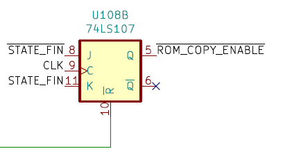
Comparing this to the original breadboard circuit:
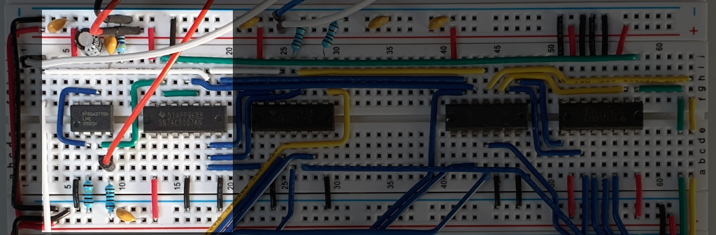
it's pretty obvious that the ROM_COPY_ENABLE line is
supposed to be connected to Q (pin 6), not Q (pin
5). Another trace cut with a knife, another bodge wire soldered on, and with that done we had some
good progress. The bit counters now worked, though I spent some time trying to work out why the
BIT_CNT3 signal was a single-cycle pulse instead of a normal count, before remembering that this
was a (deliberate) side effect of resetting the counter when we hit bit 8:
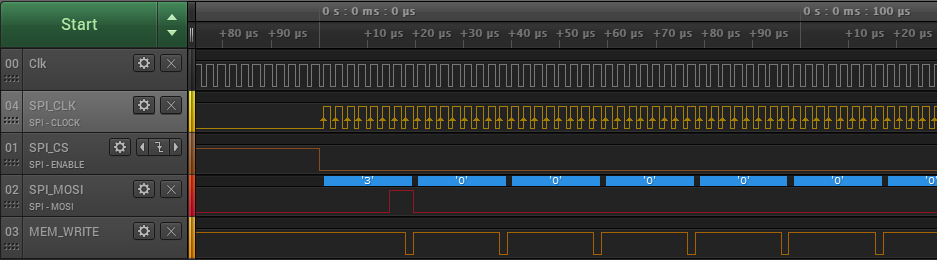
The principal remaining problem now was that the SPI_MOSI line, which is supposed to send the
first byte value 3 to the ROM chip, then stay low, was returning high as soon as the first byte
finished. Cue yet another dumb mistake:
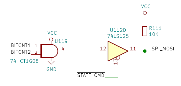
That should be a pull-down resistor, not a pull-up one. With the line being pulled high, as soon
at the command state finished (which happens after we've sent 8 bits) the 125 driver releases the
SPI_MOSI line, and it's pulled back high. After the third cut-and-solder operation, I finally had
a more-or-less working reset circuit. The SPI clock looks good, the command is being sent
correctly, and the ~WE signal that the RAM chips will need looks good too:
There are still a couple of issues to fix, but I'm leaving them for another day:
- the
SPI_CLKandSPI_CLK_INTlines should have pull-down resistors on them, so they have a clear value after the reset has finished. Leaving these floating is going to cause problems later on. - I'm seeing very occasional transient high blips on the chip-select lines during the copy, which I can't track down. They're short-enough duration that my logic probe's digital sampler sees them, but its analogue sampler isn't high-frequency enough. Without an oscilliscope it's hard to see what's happening.